
- My presentations

Auth with social network:
Download presentation
We think you have liked this presentation. If you wish to download it, please recommend it to your friends in any social system. Share buttons are a little bit lower. Thank you!
Presentation is loading. Please wait.
Optical Fiber Communications
Published by Kellie Hunt Modified over 6 years ago
Similar presentations
Presentation on theme: "Optical Fiber Communications"— Presentation transcript:
COMPUTER NETWORK TOPOLOGIES
Connection-Oriented Networks – Wissam FAWAZ1 Chapter 2: SONET/SDH and GFP TOPICS –T1/E1 –SONET/SDH - STS 1, STS -3 frames –SONET devices –Self-healing.

What is a network? A network consists of two or more computers that are linked in order to share resources (such as printers and CD-ROMs) , exchange.

Eighth Edition by William Stallings

Lecture: 4 WDM Networks Design & Operation

Optical communications & networking - an Overview

Optical Fiber Communications Optical Networks. Network Terminology Stations are devices that network subscribers use to communicate. A network is a collection.

Chapter 8 Photonic Networks. Contents Basic Networks SONET/SDH Standards Broadcast & Select WDM Networks Wavelength-Routed Networks.

Chapter 4 Circuit-Switching Networks

Fiber-Optic Networks Xavier Fernando Ryerson Communications Lab.

Department of Computer Engineering University of California at Santa Cruz Networking Systems (1) Hai Tao.

Fiber-Optic Communications

Network topology.

1 25\10\2010 Unit-V Connecting LANs Unit – 5 Connecting DevicesConnecting Devices Backbone NetworksBackbone Networks Virtual LANsVirtual LANs.

1 Introduction to Optical Networks. 2 Telecommunications Network Architecture.

Workshop IP/Optical; Chitose, Japan; 9-11 July 2002 OTN Equipment and Deployment in Today’s Transport Networks Session 5 Dr. Ghani AbbasQ9/15 Rapporteur.

Telecommunications for the future - 2 Rob Parker CERN IT Division.

TTM1 – 2013: Core networks and Optical Circuit Switching (OCS)

Fiber-Optic Network Architectures. OSI & Layer Model This Course.
About project
© 2024 SlidePlayer.com Inc. All rights reserved.
Fiber Optics Communications
Mar 22, 2019
280 likes | 668 Views
Fiber Optics Communications. Topics. Fiber Materials Fiber Manufactoring. Fiber Materials. Requirements for optical fiber material It must be possible to make long thin, flexible fibers from the material
Share Presentation
- glass fiber
- optical fiber
- vapor deposition
- halide glass fiber
- solid transparent rod preform

Presentation Transcript
Topics • Fiber Materials • Fiber Manufactoring
Fiber Materials • Requirements for optical fiber material • It must be possible to make long thin, flexible fibers from the material • Material must be transparent at a particular optical wave length in order for fiber to guide light efficiently • Physically compatible materials that have slightly different refractive indices for core and cladding must be available
Fiber Materials • Materials that satisfy these requirements are glasses and plastic • Majority of fibers are made of glass consisting of either silica or silicate. • Plastic fibers are less widely used because of their higher attenuation • Plastic fibers are used for short distance applications (several hundred meters) and abusive environments
Glass Fiber • Glass is made by fusing mixture of metal oxides, sulfides, or selenides. The resulting material is a randomly connected molecular network rather a well defined structure as found in crystalline materials • A consequence of this random order is glass does not have a well defined melting point • When glass is heated , it gradually begins to soften until it becomes a viscous liquid
Glass Fiber • Optical fiber are made from oxide glasses and most popular is silica (SiO2) which has refractive index of 1.458 at 850 nm. • To produce two similar materials with slightly different refraction indices for core and cladding, either fluorine or other oxides (dopants) are added to silica
Glass Fiber • Sand is the principle raw material for silica • Glass composed of pure silica is referred to as either silica glass, fused glass, or vitreous silica. • Desired properties are • resistance to deformation at temperatures as high as 1000 C • High resistance to breakage from thermal shock • Good chemical durability • High transparency in both visible and infrared regions of interest
Plastic Optical Fibers • Growing demand for delivering high-speed services to workstations • Have greater optical signal attenuations than glass fiber • They tough and durable • Core diameter is 10-20 times larger
Fiber Fabrication • Two basic techniques • Vapor-phase oxidation process • Outside vapor phase oxidation • Vapor phase axial deposition • Modified chemical vapor deposition • Direct-melt methods
Fiber Fabrication • Direct melt method • Follows traditional glass making procedures • Optical fiber are made directly from molten state of purified components of silicate glass • Vapor phase oxidation • Highly pure vapors of metal galides (SiCl4) react with oxygen to form white powder of SiO2 particles • Particles are collected on surface of bulk glass by above methods and are transformed to a homogenous glass by heating without melting to form a clear glass rod or tube. This rod is called preform • Preform is 10-25 mm in diameter and 60-120 cm long.
Fabrication • Prefrom is fed into circular heater called drawing furnace. • Preform end is softened to the point where it can be drawn into a very thin filament which becomes optical fiber • The speed of the drum at the bottom of draw tower determines how fast and in turn how thick the fiber is • An elastic coating is applied to protect the fiber
Outside Vapor Phase Oxidation • Core layer is deposited on a rotating ceramic rod • Cladding is deposited on top of core layer • Ceramic rod is slipped out (different thermal expansion coefficient) • The tube is heated and mounted in a fiber drawing tower and made into a fiber • The central hole collapses during this drawing process
Vapor Phase Axial Deposition • Similar to outside vapor deposition • Starts with a seed which is a pure silica rod • The preform is grown in the axial direction by moving rod upward • Rod is also rotated to maintain cylindrical symmetery • As preform moves upward it is transformed into a solid transparent rod preform by zone melting (heating in a narrow localized zone) • Advantages • No central hole
Modified Chemical Vapor Deposition • Pioneered at Bell Labs, and adopted to produce low loss graded index fiber • Glass vapor particles, arising from reaction of constituent metal halide gasses and oxygen flow through inside of revolving silica tube • As SiO2 particles are deposited, they are sintered to a clear glass layer by an oxyhydrogen torch which travels back and forth • When desired thickness of glass have been deposited, vapor flow is shut off • Tube is heated strongly to cause it to collapse into a solid rod prefrom • Fiber drawn from this prefrom rod will have a core that consists of vapor deposited material and a cladding that consists of original silica tube.
Double Crucible Method • Silica and halide glass fiber can all be made using a direct-melt double crucible technique • Glass rods for the core and cladding materials are first made separately by melting mixtures of purified powders • These rods are then used as feedstock for each of two concentric crucibles • Advantage of this method is being a continuous process • Careful attention must be paid to avoid contaminants during metling
- More by User

Fiber Optics
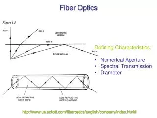
Fiber Optics. Defining Characteristics: Numerical Aperture Spectral Transmission Diameter. http://www.us.schott.com/fiberoptics/english/company/index.html# . Are you getting the concept?. Light of vacuum wavelength l 0 = 850.0 nm enters the end of an optical
809 views • 39 slides
Fiber Optics. PLASTIC OPTICAL FIBER (POF). Fiber Optics. Plastic optical fiber (POF) has always been "lurking in the background" in fiber optics, a specialty fiber useful for illumination and low speed short data links. . Fiber Optics.
619 views • 0 slides
Fiber Optics. TESTING MULTIMODE FIBER. Fiber Optics. O ne of the first things a technician should do is test the fiber reel for light continuity before installing the fiber optic cable. T his is done by simply shining a flash light thru all the strands to make sure there are no dark fibers.
965 views • 26 slides

Fiber Optics. PULLING FIBER OPTIC CABLES. Fiber Optics. One of the most critical steps before pulling fiber is to get an accurate measure of the distance of the cable pull, we usually add approximately 20% to this total for a fudge factor.
552 views • 28 slides

Fiber Optics. FIBER OPTIC CABLE CONSTRUCTION. Fiber Optics. We’ve already looked at the difference between SM and MM fiber and the core, cladding and buffer differences between them. That is the preliminary composition of fiber.
694 views • 21 slides

Fiber Optics. FIBER CONNECTOR TYPES. Fiber Optics. There have been many different types of fiber optic connectors developed throughout the years, many of which are now obsolete.
698 views • 25 slides

Fiber Optics. EPOXY/POLISH TERMINATIONS. Fiber Optics. A WORD OF CAUTION WHEN TERMINATING FIBER. THERE ARE SPECIFIC SAFETY PROCEDURES THAT NEED TO BE FOLLOWED. Fiber Optics. FIBER OPTIC SAFETY RULES : KEEP ALL FOOD AND DRINKS OUT OF THE WORK AREA ALWAYS WEAR SAFETY GLASSES .
958 views • 39 slides

Fiber Optics. BASIC FIBER OPTIC LINK. Fiber Optics. Fiber optic transmission systems consist of a transmitter that takes an electrical signal and converts it into an optical signal from a laser or LED and couples the light into an optical fiber.
524 views • 22 slides
FIBER OPTICS COMMUNICATIONS
FIBER OPTICS COMMUNICATIONS. Zhi Li, Hui Li, Yiwen Qin and Chris Kong. Fiber optics.
393 views • 13 slides

Fiber Optics. LINK LOSS BUDGET. Fiber Optics. In order to operate properly, a fiber optic network link must have an adequate loss margin. The total loss in the installed cable plant must be less than the tolerable loss of the transmitters and receivers used in the fiber optic link.
646 views • 21 slides

Fiber Optics. FUSION SPLICING. Fiber Optics. Fusion splicing is the process of fusing or welding two fibers together usually by an electric arc .
590 views • 26 slides

Fiber Optics. FIBER OPTIC PATCH PANELS. Fiber Optics. Just like our copper cable plant the fiber cable plant incorporates many of the same hardware components and patch panels.
461 views • 24 slides

Fiber Optics. LIGHT CRIMP TERMINATIONS USING THE PRENTIUM KIT. Fiber Optics. Terminating fiber has always been considered the most difficult part of installing a fiber optic cable plant.
573 views • 30 slides

Fiber Optics. OPTICAL TIME DOMAIN REFLECTOMETER (OTDR). Fiber Optics. An Optical time domain reflectometer (OTDR) is used to test a fiber optic cable by injecting a series of high powered optical pulses into the fiber under test .
548 views • 30 slides

FIBER OPTICS
FIBER OPTICS. A TECHNICAL SEMINAR By RAHUL GUPTA Instructor MISS. NAZIA KHAN. INTRODUCTION
382 views • 13 slides

Fiber Optics. MULTIMODE VS. SINGLEMODE FIBER. Fiber Optics. When we talk about fiber we refer to either multimode or singlemode fiber. We further clarify the types by their core and cladding size. The core and cladding numbers will be listed on the cable jackets…………. Fiber Optics.
424 views • 20 slides

Fiber Optics. History of Fiber Optics.
807 views • 58 slides

Fiber Optics. By Matt Bayliss Jerome Carpenter. History and Background. Techniques of Total Internal Reflection first used by Greek and Venetian glass blowers centuries ago.
283 views • 15 slides

Fiber Optics Communications. Lecture 11. Signal Degradation In Optical Fibers. We will look at Loss and attenuation mechanism Distortion of optical signals. contd. Signal attenuation (fiber loss) determines maximum unamplified or repeaters separation between a transmitter and a receiver
448 views • 25 slides
Fiber Optics in Communications and Computing
Fiber Optics in Communications and Computing. Peter Persans Physics Dept., SC1C10, persap. Trans-Atlantic Communications - 1866. 10 words/min. Trans-Atlantic Communications: 1998. 10 13 words/min. A prototypical fiber system. Elements of a communications system. signal source
114 views • 9 slides
- Preferences

Fiber-Optic Communications - PowerPoint PPT Presentation

Fiber-Optic Communications
Fiber-optic communications james n. downing chapter 9 fiber-optic communications systems 9.1 system design considerations design is based on application type of ... – powerpoint ppt presentation.
- James N. Downing
- Fiber-Optic Communications Systems
- Design is based on
- Application
- Type of signal
- Distance from transmitter to detector
- Performance standards
- Resource constraints (time, money, etc.)
- Implementation
- Format, power, bandwidth, dynamic range
- Amplification
- Amplification, amplitude, and spacing
- Multiplexing
- Security requirements
- Acceptable noise levels
- System Power Budget
- Most important parameter is throughput or transfer function.
- Output power must be greater than the input sensitivity of the receiver.
- System budget
- Amount of power lost or gained in each component
- System power margin
- Allows for component tolerances, system degradation, repairs and splices
- Power at the Source
- Transmitter must be appropriate for the application
- Number of signals
- Wavelength of signal
- Type of transmitter device (LED, Laser)
- Mode structure
- WDM and amplification capability
- Coupling efficiency
- Power in the Fiber
- Source output pattern, core-size, and NA of fiber
- Coupling is critical
- Power at the Detector
- Sensitivity is the primary purpose of the detector
- Minimum sensitivity yet still meets standards
- Must support the dynamic range of the power levels
- Fiber Amplification
- For those fibers that require amplification
- Repeaters are rarely used.
- Optical amplifiers are the preferred amplification.
- Use manufacturers specifications to ensure optimization of the input signal.
- Amplifier Placement
- Type of amplifier
- Transmitter
- Noise and error analysis
- Can be inserted
- Before regeneration
- Between regenerators
- System Rise Time Budget
- Determines the bandwidth carrying capability
- Total rises time is the sum of the individual component rise times.
- Bandwidth is limited by the component with the slowest rise time.
- Rise Time and Bit Time
- Rise time is defined as the time it takes for the response to rise from the 10 to 90 of maximum amplitude.
- Fall time is the time the response needs to fall from 90 to 10 of the maximum.
- Pulse width is the time between the 50 marks on the rising and falling edges.
- Transmitters, Receivers, and Rise Time
- Rise time of transmitter is based on the response time of the LED or laser diode.
- Rise time of the receiver is primarily based on the semiconductor device used as the detector.
- Fiber Rise Time
- Comes directly from the total dispersion of the fiber as a result of modal, material, wave guide, and polarization mode dispersion
- Total Rise Time
- Sum of all the rise times in the system
- Round Trip Delay
- Time needed for the signal to reach the furthest point of the network and return
- Dispersion Compensation
- Allows for lowering the fiber dispersion characteristics
- add fiber with dispersion of the opposite magnitude
- Only available type chromatic dispersion
- Single Channel System Compensation
- Long length of small amplitude dispersion fiber
- Short length of large amplitude dispersion fiber (distributed compensation)
- Multi-Channel System Compensation
- Large effective area fibers
- Reduced dispersion fibers
- Noise and Error Analysis
- Determines the type of amplification required
- Minimizing System Noise
- Additional Noise Sources
- Extended pulse width
- Modal properties of fibers
- Fresnel reflection
- Feedback noise
- Multiple Channel System
- Channel Density and Spacing
- Standards have been defined by ITU-T
- WDM, TDM, and Noise
- Interchannel crosstalk Data from adjacent channels gets mixed
- Dispersion in adjacent channels
- Non-linearities at high powers causes interference
- Narrow bandpass filtering at the receiver
- WDM Power Management
- Methods must ensure that all power levels fall with acceptable range.
- Gain flattening is the process of adjusting the amplitudes of wavelengths to be the same.
- Long-Haul Communications
- Terrestrial cables
- Telegraph cable across the English Channel in 1850
- First transatlantic cable in 1866
- Transatlantic telephone cable in 1957
- Transatlantic fiber-optic cable in 1988
- Optical amplifiers replaced repeaters in 1990s
- Undersea Cables
- Must be capable of low loss and dispersion
- Must limit optical noise
- Must have a pressure resistant covering
- Amplifier gain below 10 dB
- Precise dispersion
- Repeatered systems has pump laser and amplifier
- Unrepeatered system has optical amplifiers spaced out over the length of the fiber
- Terrestrial Cables
- Long-haul lengths
- Easy repair
- Amplification needed less often
- When is terrestrial, satellite or undersea cabling used?
- Depends on politics and economy rather than technology or geography
- Metro and Regional Networks
- PSTN Public switched telephone networks for regions (little population)
- MANs Metropolitan area networks (more densely populated areas such as towns and universities)
- LANs Local area networks
- WANs Wide area networks
- Soliton Communications
- Form of dispersion compensation
- Combination of chromatic and self-phase modulation
- Coherent Communications Systems
- Uses WDM bandwidth more efficiently
- Possible improvement in receiver sensitivity
- Optical CDMA
- Maximizes the bandwidth in LANs without special filtering devices
- Spreads the signal energy over a wider frequency band than necessary
- Free Space Optics
- Signal travels through space rather than a fiber
- Relies on line of sight
- Free of FCC regulations
- Bandwidth is not held to that of the fiber used
- Fiber Optics and the Future
- Where you go, then so shall I.
PowerShow.com is a leading presentation sharing website. It has millions of presentations already uploaded and available with 1,000s more being uploaded by its users every day. Whatever your area of interest, here you’ll be able to find and view presentations you’ll love and possibly download. And, best of all, it is completely free and easy to use.
You might even have a presentation you’d like to share with others. If so, just upload it to PowerShow.com. We’ll convert it to an HTML5 slideshow that includes all the media types you’ve already added: audio, video, music, pictures, animations and transition effects. Then you can share it with your target audience as well as PowerShow.com’s millions of monthly visitors. And, again, it’s all free.
About the Developers
PowerShow.com is brought to you by CrystalGraphics , the award-winning developer and market-leading publisher of rich-media enhancement products for presentations. Our product offerings include millions of PowerPoint templates, diagrams, animated 3D characters and more.


IMAGES
VIDEO
COMMENTS
Chapter One: Introduction to Fiber Optics Communication System. What is Fiber Optic?. Fiber optics - A means to carry information from one point to another or serves as transmission medium (optical fiber).
Presentation Transcript. Optical Fiber Communications Lecture 10. Topics • Single Mode Fiber • Mode Field Diameter • Propagation Modes in Single Mode Fiber • Graded Index Fiber. Single Mode Fiber • Single Mode fiber are constructed by • letting dimensions of core diameter be a few wavelengths and • by having small index difference ...
OPTICAL FIBER COMMUNICATION. Introduction . A communication system transmits information (voice, picture, data etc) from one place to another. Information is often modulated by carrier waves whose frequency can vary from a few megahertz to several hundred Terahertzes. Download Presentation basic optical communication system light output purpose ...
Fiber-optic communication is a method of transmitting information from one place to another by sending light through an optical fiber. The light forms an electromagnetic carrier wave that is modulated to carry information.
Presentation on theme: "Fiber-Optic Communication Systems An Introduction"— Presentation transcript: 1 Fiber-Optic Communication Systems An Introduction. 2 History of Fiber Optics. John Tyndall demonstrated in 1870 that Light can be bent Total Internal Reflection (TIR) is the basic idea of fiber optic. 3 Why Optical Communications?
The fiber which are used for optical communication are wave guides made of transparent dielectrics. Its function is to guide visible and infrared light over long distances. 4 Structure of optical fiber. 5 Core - central tube of very thin size made up of optically transparent dielectric medium and carries the light form transmitter to receiver.
Fiber-Optic Communication Systems An Introduction - PowerPoint PPT Presentation Remove this presentation Flag as Inappropriate I Don't Like This I like this Remember as a Favorite Download Share
Fiber Optic Communication By. Description: Fiber Optic Communication By Engr. Muhammad Ashraf Bhutta Lecture Outlines SDH Overview Frame structure and multiplex-ing methods Overheads and Pointers SDH Overview ... - PowerPoint PPT presentation. Number of Views: 198. Avg rating:3.0/5.0. Slides: 58.
Fiber-Optic Communications. James N. Downing. Chapter 3. Characteristics of Optical Fibers. Chapter 3 Characteristics of Optical Fibers. 3.1 Light Propagation in Optical Fibers Acceptance Angle and Numerical Aperture Acceptance angle is the angle cone of light transmitted down the fiber.
Optical Fiber Communications Optical Networks 15 16 17 18 19 20 22 WDM Multi-hop Architecture Four node broadcast and select multihop network Each node transmits at ... - A free PowerPoint PPT presentation (displayed as an HTML5 slide show) on PowerShow.com - id: 40d053-MGVmN
Network Terminology Stations are devices that network subscribers use to communicate. A network is a collection of interconnected stations. A node is a point where one or more communication lines terminate. A trunk is a transmission line that supports large traffic loads. The topology is the logical manner in which nodes are linked together by information transmitting channels to form a network.
Fiber-Optic Communications. James N. Downing. Chapter 7. Fiber-Optic Devices. 7.1 Optical Amplifiers. Repeaters and Regenerators Repeater An optical receiver converts the light to an electrical signal. An amplifier increases the signal.
The cable consists of one or more glass fibers, which act as waveguides for the optical signal. Fiber optic cable is similar to electrical cable in its construction, but provides special protection for the optical fiber within. For systems requiring transmission over distances of many kilometers, or where two or more fiber optic cables must be joined together, an optical splice is commonly ...
Optical Fiber Communications An Image/Link below is provided (as is) to download presentation Download Policy: Content on the Website is provided to you AS IS for your information and personal use and may not be sold / licensed / shared on other websites without getting consent from its author. Download presentation by click this link. While downloading, if for some reason you are not able to ...
Fiber-Optic Communications James N. Downing Chapter 4 Fiber and Cable Fabrication 4.1 Optical Fiber Fabrication Fused Silica Glass Medium of choice for fiber ... - A free PowerPoint PPT presentation (displayed as an HTML5 slide show) on PowerShow.com - id: 429a86-NGNkM
Presentation Transcript. Fiber Optics Technology. Optical Communication Systems • Communication systems with light as the carrier and optical fiber as communication medium • Optical fiber is used to contain and guide light waves • Typically made of glass or plastic • Propagation of light in atmosphere is impractical • This is similar ...
Presentation Transcript. Fiber Materials • Materials that satisfy these requirements are glasses and plastic • Majority of fibers are made of glass consisting of either silica or silicate. • Plastic fibers are less widely used because of their higher attenuation • Plastic fibers are used for short distance applications (several hundred ...
Fiber-Optic Communications James N. Downing Chapter 9 Fiber-Optic Communications Systems 9.1 System Design Considerations Design is based on Application Type of ... - A free PowerPoint PPT presentation (displayed as an HTML5 slide show) on PowerShow.com - id: 47dbe8-OGY4Z